TVC Rocket Development
April 2026 - Present
Designed for: Fun / Curiosity
Motivation
I started this project with a desire to build a rocket. I didn’t want to build a model rocket kit or a typical rocket as my desire was to challenge myself. While looking at rocket videos online, I came across the concept of Thrust Vector Control rockets and a few channels that really solidified my desire to build one myself.
Thrust Vector Control
Before I get ahead of myself, let me explain what Thrust Vector Control (TVC) is. When a rocket is launched, the force that is exerted on the rocket in an upwards direction is called thrust. This force is actually a reaction force against the rocket that occurs when a motor is burned and it exerts a force from the motor onto the atmosphere.
TVC controls the direction of the rocket by controlling the thrust, or the direction of the thrust vector. It is called thrust VECTOR control rather than thrust control because the magnitude of the thrust cannot be controlled. Instead, we control only the direction of the thrust vector (yes i repeated myself).
TVC can help model rockets achieve higher altitudes.
My research delves into the types of TVC systems used in model rockets and of course my sources.
Research and Development
I looked at a few main sources: BPS space’s How To Build a Thrust Vectored Model Rocket - National Rocketry Conference 2020 video and his various other videos This source was great for understanding the process of designing and building your very own TVC rocket. It had a lot of great advice and is a very in depth video. This video definitely showed me that the hard part would be coding. However, I decided not to go with one of the readily available open source designs online and design my own, so that may add difficulty to that part of the project.
This article from aerospace notes This article describes really well types of TVC, although many are not quite feasible on model rockets. They have nice diagrams as well. Gimbal/Hinge is that one I wanted to go with, but some other common ones are jet vanes/tabs, and side injection. These other methods are also covered in the apogee rocket newsletter linked next. One thing to note is the key difference between moving the entire motor and then only the plume (the stuff that comes out of the motor). It is better to move the plume or gimbal the motor at the nozzle, because it is where the force is actually exerted and will lead to more accurate/real time effects when being controlled.
Apogee rockets newsletter article 515 This article goes into the limitations and methods of implementing Enhanced Flight Control systems on model rockets. I learned that I want a slow burn system for full effect of thrust control (thrust control is useless if fuel is used up as it no longer exerts a force on the rocket in any direction) Vernier thrusters (completely separate from TVC) for attitude control are not very well researched for model rockets, but could be interesting. Would not implement in this project. Control fins are also mentioned.
For now I am not doing much actual rocket research because I want to focus on the TVC. I do know a bit from past interest in rocketry and I do believe I know enough to complete the TVC. My plan is to finish the TVC, work on the avionics bay, add parachute systems and a nosecone, and then do necessary simulations.
A lot of my research past these few main sources were looking into other people’s designs and taking inspiration. A big inspiration was L Shang.
Initial designing
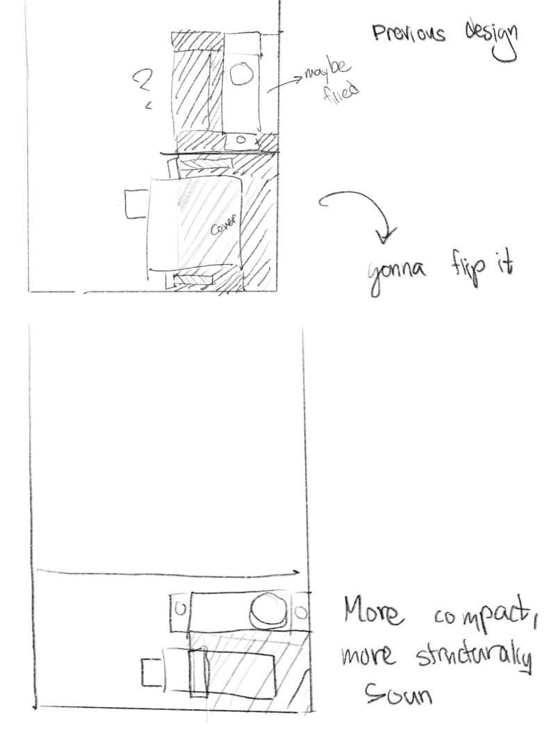
Before I even CADed anything I made quite a few sketches on my iPad.

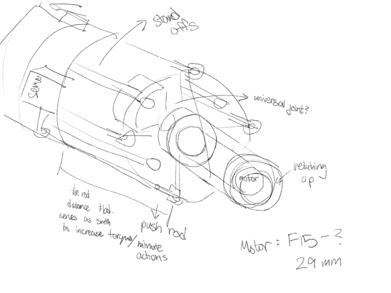
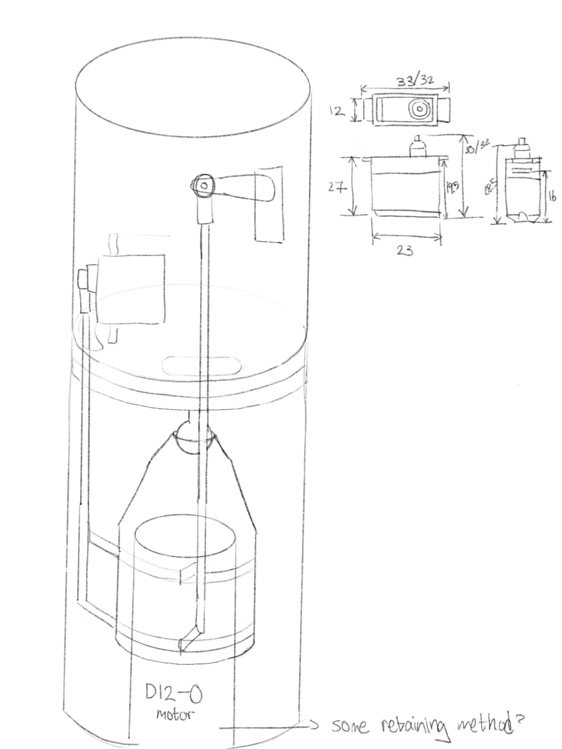
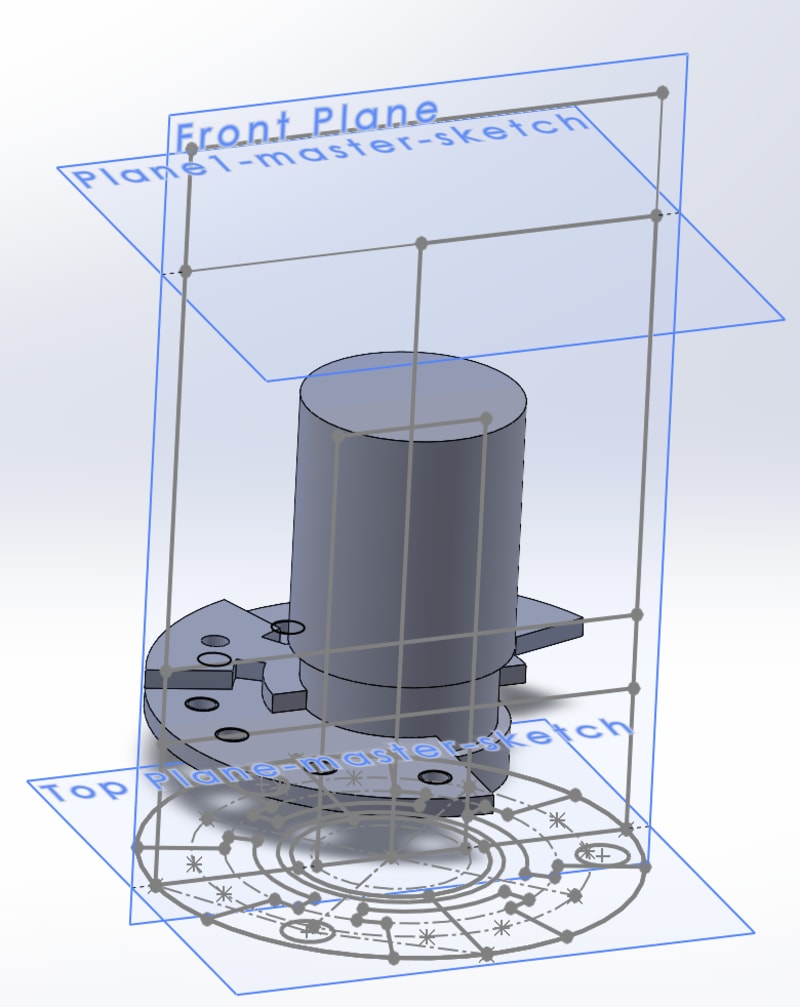
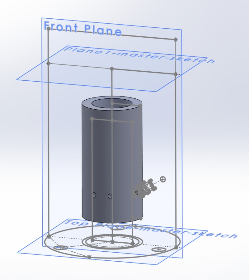
I started with a master sketch that had all the geometry I would need to reference, and then split the TVC into 3 main parts. The first part is the servo mount, the second is the gimbal interface, and the third is the motor mount.

I started with the servo mount as that’s where all the motion comes from. This was more difficult than I imagined to start with, and the placement really confused me for the first day. It definitely made more sense as I finished the first iteration and realized I had it completely wrong.
I made another copy and I was quite happy with it all except for the space utilisation.

I happened to be with a friend that day and talked about this project, and he suggested a totally different arrangement that blew my mind completely. I made another version with his suggestion, and it worked tremendously better than I could have imagined.
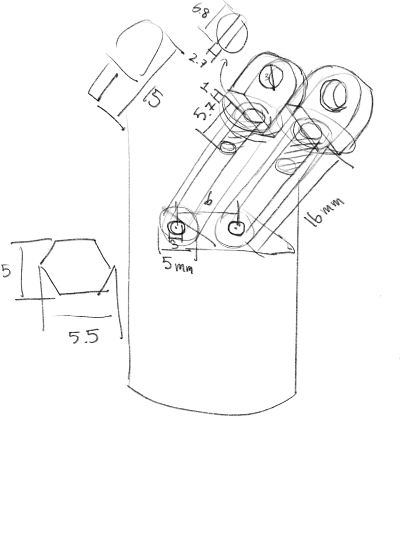
Currently, I am struggling a lot with the motor mount and have gone back and forth with a lot of designs. The big issue is manufacturing. 3D printing is not suitable due to the heat from the motor, not even ABS, and the shapes I need are so irregular that it is difficult to make with services like sendcutsend, which only does flat sheet metal and bending. Furthermore, attaching the gimbal would be incredibly difficult because of the weird thread size (15/16-27) as it’s a faucet standard and not a standard anywhere else. (I purchased a 360 degree swivel aerator to use as the gimbal, which uses universal faucet threads).

With my first attempt, I thought it would be easiest to use rings cut out of sheet metal, as it was easy to source. Two issues occurred: The ring was too big, it was sized to the very edge of the airframe and would not gimbal at all (woops!) and…how was I going to case the cylinder!
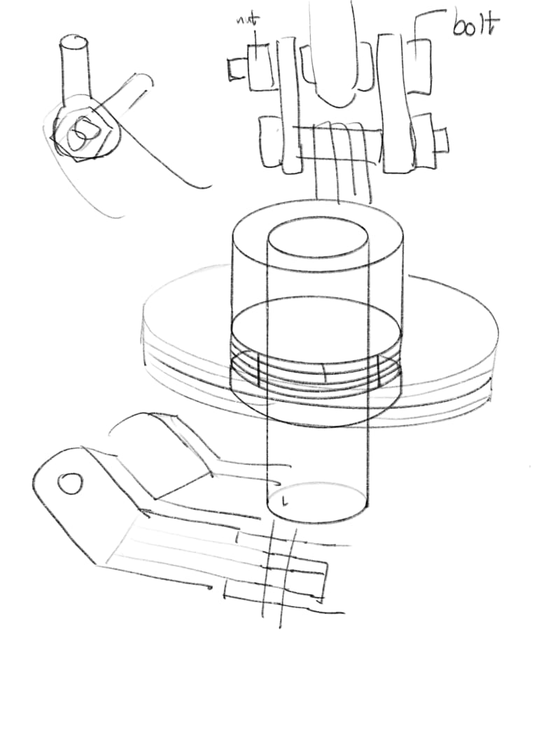
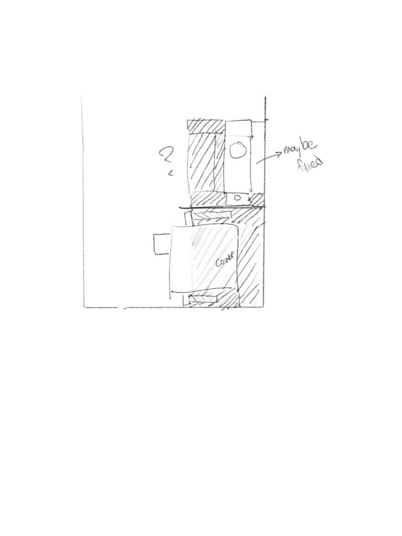
With my second attempt, I decided that I would just have two little prongs stick out at four places. These spokes are 90 degrees from each other and would be secured by some sort of bolt. I gave up after realizing it would be almost impossible to attach the prongs to the cylinder.
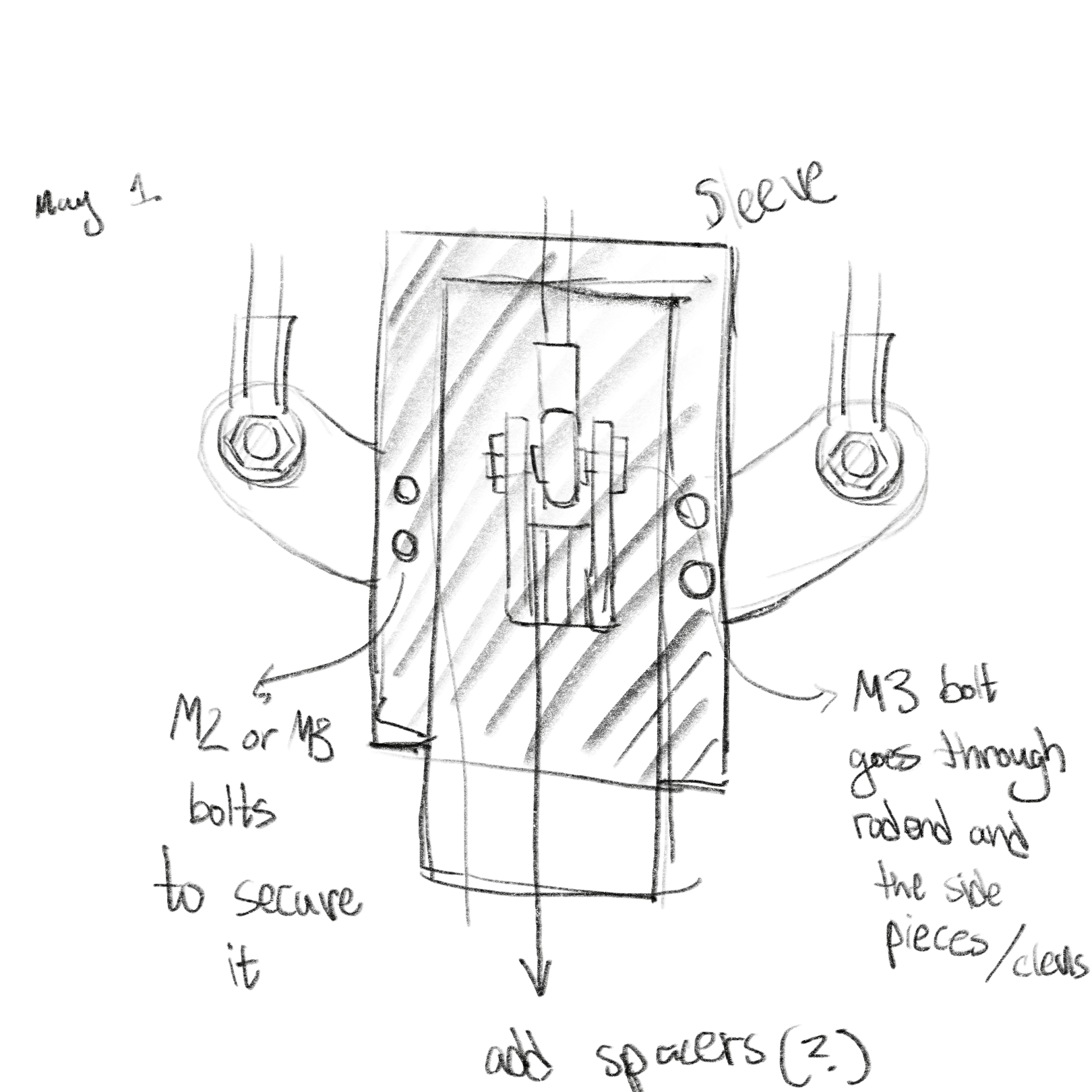
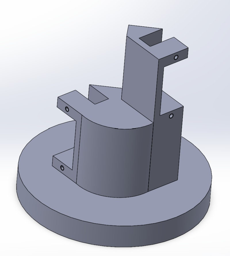
With my third attempt, I decided that I would again have two little prongs stick out at four places. It would be a very similar layout, but instead I would use threaded rods. These will also serve nicely as set screws to retain the motor. The only issue here is that they would have to be drilled at an angle and tapped at an angle, in addition to the main issue noted at the start. This is by far my best shot and I will work with this as a 3D print and then get my materials to work with it.
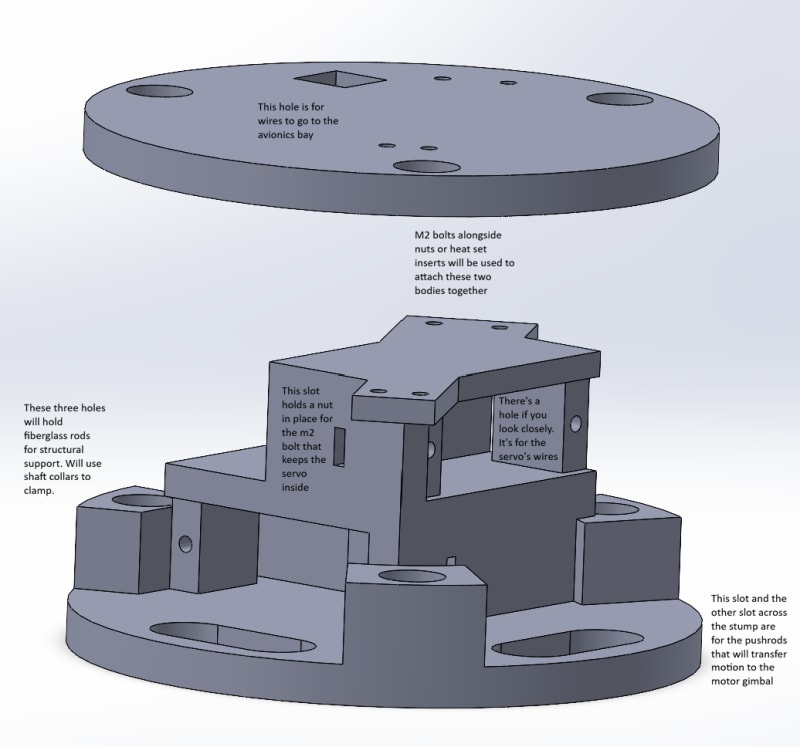
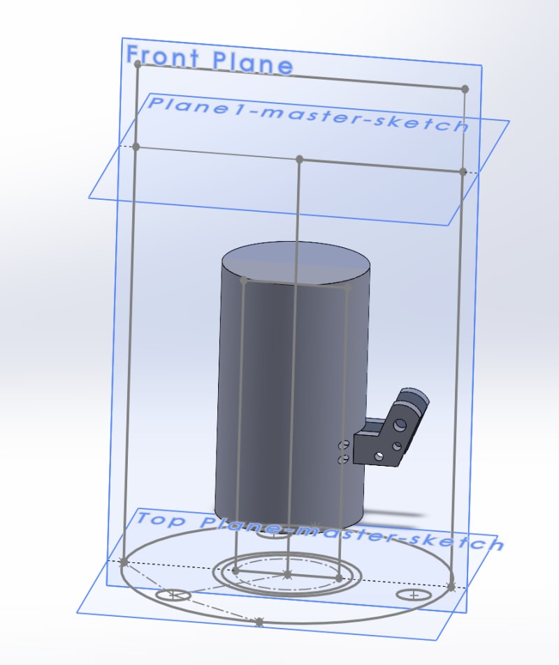
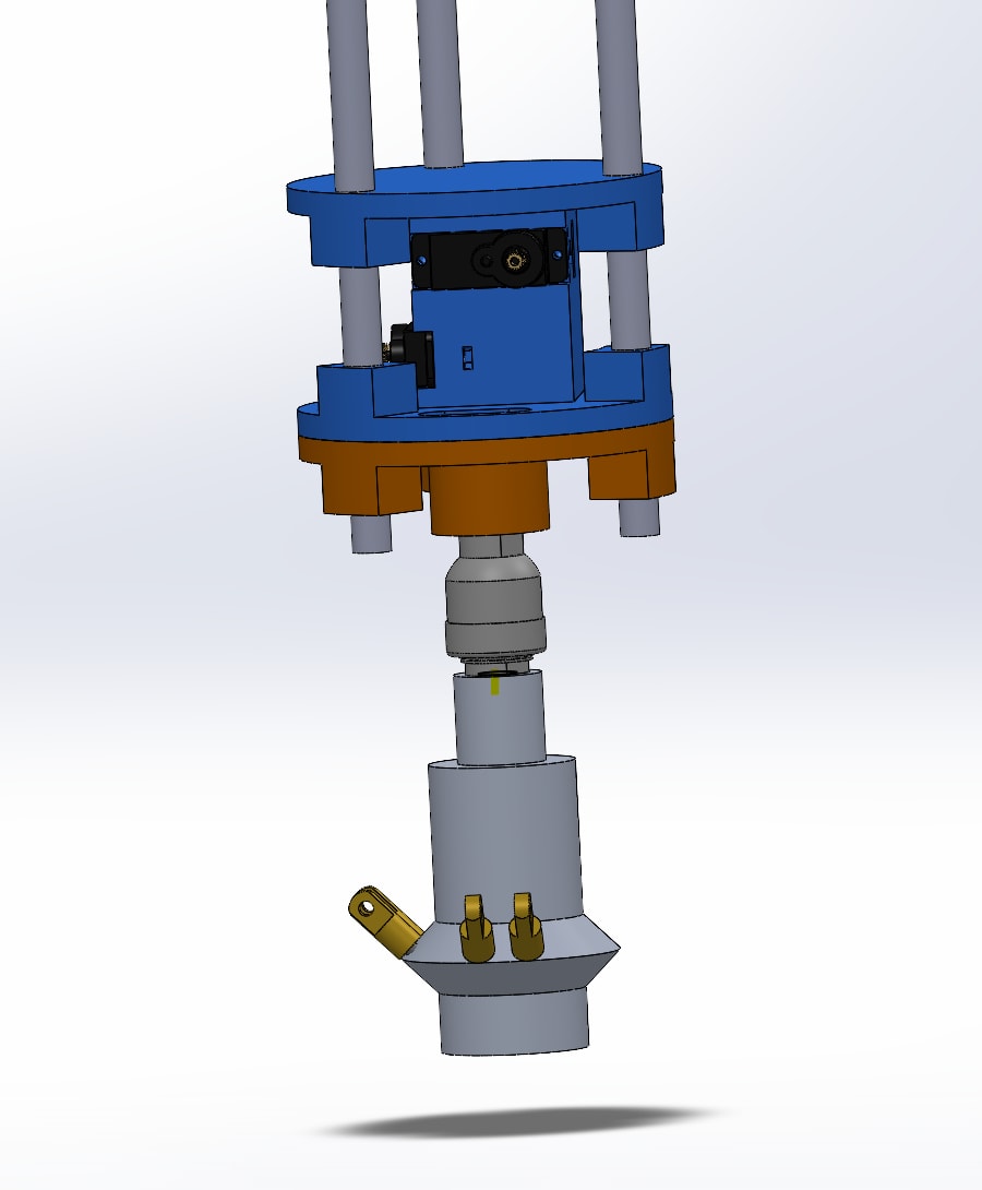
This is the latest assembly, I forgot to take pictures of the last few unfortunately. There has been a LOT of changes to pretty much every part either for decreasing weight, price, fixing a problem, or manufacturing. I am at a point where I unfortunately also had to make returns on aliexpress…which suck a lot. Here is a summary of my solved and unsolved issues.
| Problem | Next Steps / Possible Solutions |
|---|---|
| Push rod lengths |
|
| Servo being bootleg |
|
| Servo horns (missing or incompatible + M2 vs M3 hole mismatch) |
|
| Geometry of servo mount design Solved |
|
| Thread engagement on the spokesSolved |
|
| Acquire rail buttons Solved |
|
| Gimbal cost ( shipping cost )Solved |
|
I also need to deal with motor retention later, but I am still looking at OTS options and custom options that fit the designed motor mount.